
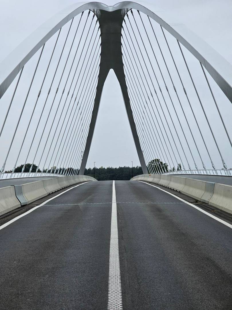
 01Concrete bridge decksI06-01 · Open evidence and annotated details →
Infrastructure Waterproofing Solutions
Roads, Bridges & Traffic-Bearing Surface Waterproofing
Waterproofing for concrete and steel bridge decks, railway bridges, viaducts, ramps and traffic platforms. The membrane, bond coat, surfacing and movement details must remain compatible under traffic and temperature cycling.
Waterproofing SolutionsInfrastructure Waterproofing SolutionsI06 Roads, Bridges & Traffic Decks
Application Scope
One system, several project conditions
These application contexts cover the principal project conditions addressed by this system. The final build-up is defined after the substrate, environmental exposure, movement and service requirements are confirmed.
01Concrete bridge decksI06-01 · Open evidence and annotated details →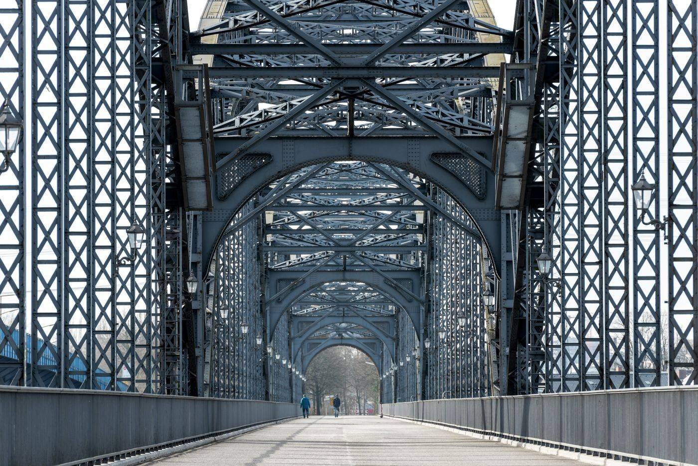 02Steel bridge decksI06-02 · Open evidence and annotated details →
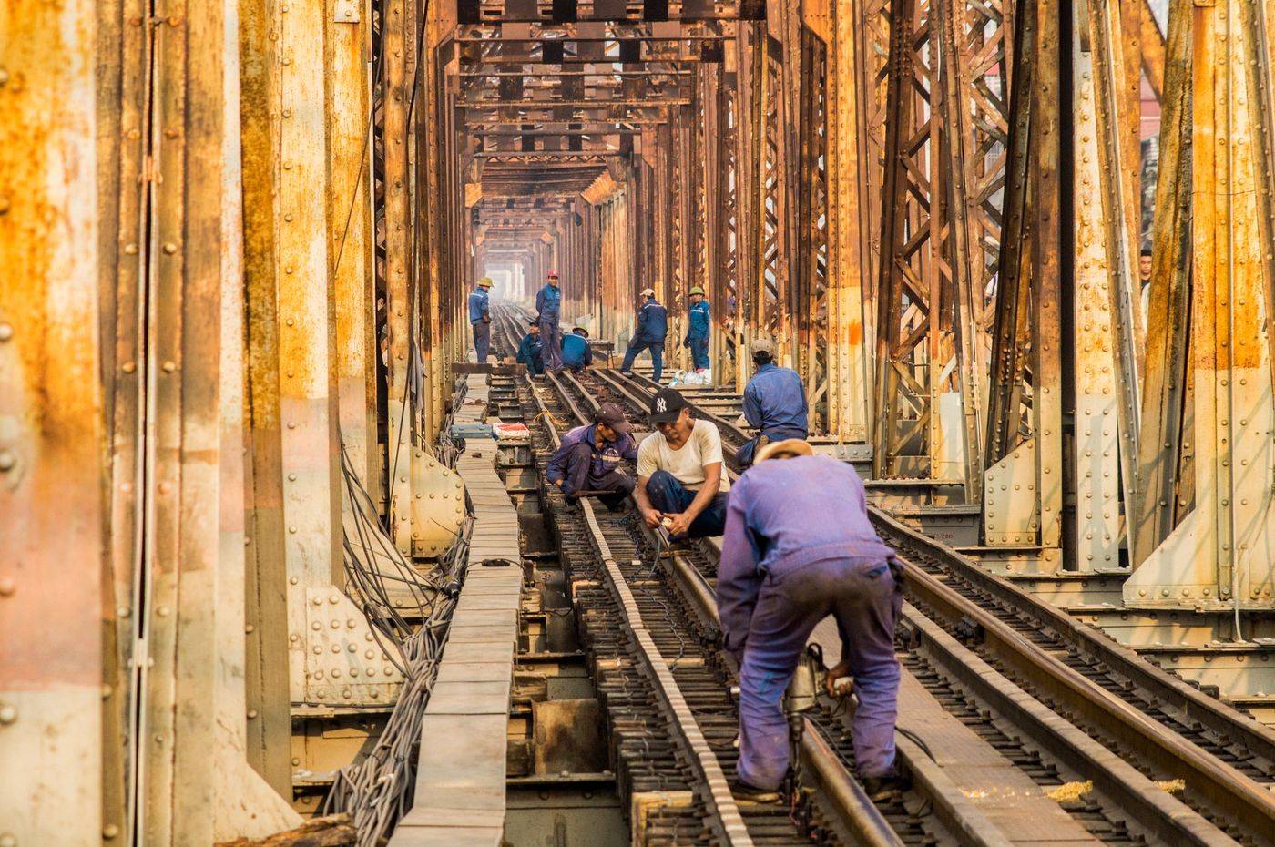 03Railway bridgesI06-03 · Open evidence and annotated details →
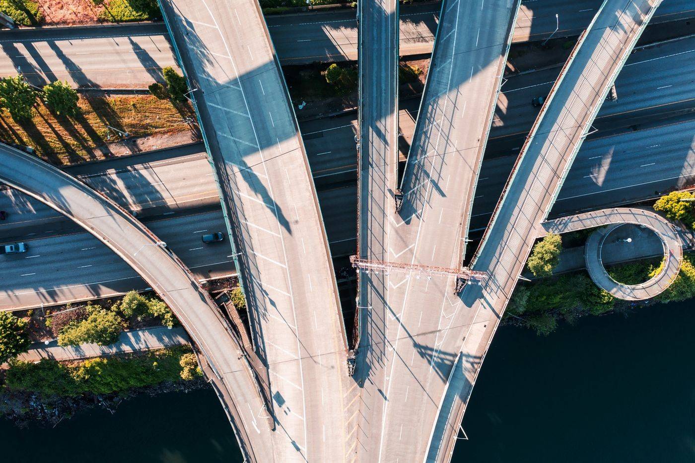 04Viaducts and rampsI06-04 · Open evidence and annotated details →
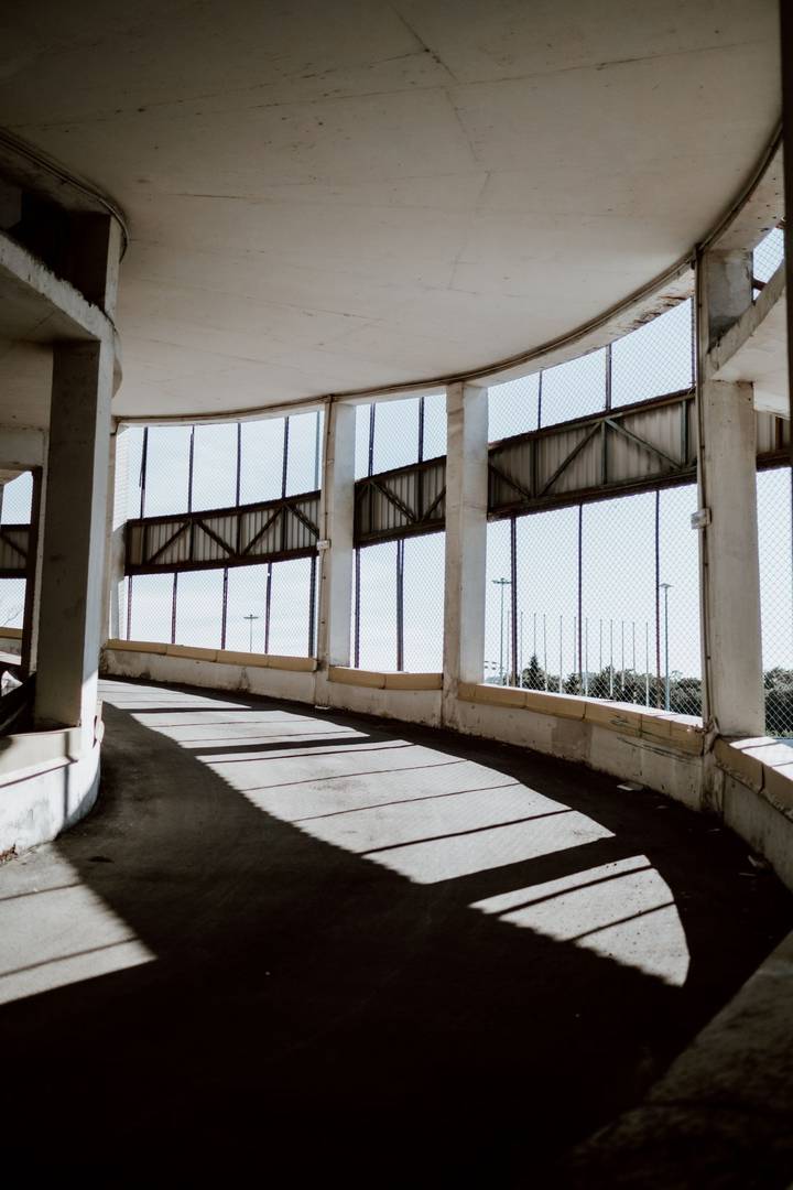 05Traffic-bearing platformsI06-05 · Open evidence and annotated details →
System Logic
Technical routes are connected to conditions
Each application context is connected to the technical routes that match its substrate, installation method, environmental exposure and detailing requirements.
Bonded membrane systems
Sheet membranes and bond coats selected for deck preparation, overlay temperature and traffic demand.
Liquid-applied deck systems
Spray or liquid membranes controlled by substrate profile, cure window and thickness.
Asphalt-compatible waterproofing layers
Waterproofing and tack or bonding layers are confirmed against the selected surfacing system.
Joint and drainage details
Expansion joints, kerbs, drains and deck edges are coordinated as critical interfaces within the waterproofing system.
System Build-Ups & Critical Details
Real application context connected to N/L annotated drawings
Every technical drawing is placed under its mapped application context. L labels identify construction layers; N labels identify critical details and interfaces. Final specifications remain project-specific.
I06-01 Application Context
Concrete bridge decks
System build-ups and critical details
L-series labels identify build-up layers. N-series labels identify critical nodes and interfaces. Open a drawing to inspect both annotation systems.
I06-02 Application Context
Steel bridge decks
System build-ups and critical details
L-series labels identify build-up layers. N-series labels identify critical nodes and interfaces. Open a drawing to inspect both annotation systems.
I06-03 Application Context
Railway bridges
System build-ups and critical details
L-series labels identify build-up layers. N-series labels identify critical nodes and interfaces. Open a drawing to inspect both annotation systems.
I06-04 Application Context
Viaducts and ramps
System build-ups and critical details
L-series labels identify build-up layers. N-series labels identify critical nodes and interfaces. Open a drawing to inspect both annotation systems.
I06-05 Application Context
Traffic-bearing platforms
System build-ups and critical details
L-series labels identify build-up layers. N-series labels identify critical nodes and interfaces. Open a drawing to inspect both annotation systems.
Visual Evidence
Application and project references
Project photographs document real construction conditions. Licensed reference photographs are labelled as context images, with AKWAX-delivered project evidence identified separately.
Decision Boundary
What must be confirmed before a route is fixed
A system proposal becomes meaningful only after these conditions are documented.
- Concrete or steel deck
- Traffic and fatigue demand
- Overlay type and paving temperature
- Deck moisture and surface profile
- Movement joints, edges and drainage
Project Discussion